Home lab with NanoBSD, APU2 and Kubernetes on Raspberry Pi - 0
Home lab.
For some time I had been thinking about building a home lab (Kubernetes cluster) with access to and from the internet so I could research and practice with the technologies I care about, using low-power components that are as resilient as possible to power outages (to avoid corruption of storage devices). To get there I reused hardware I had bought at some point simply because it interested me. Without further delay, here is a network diagram of how this lab ended up:
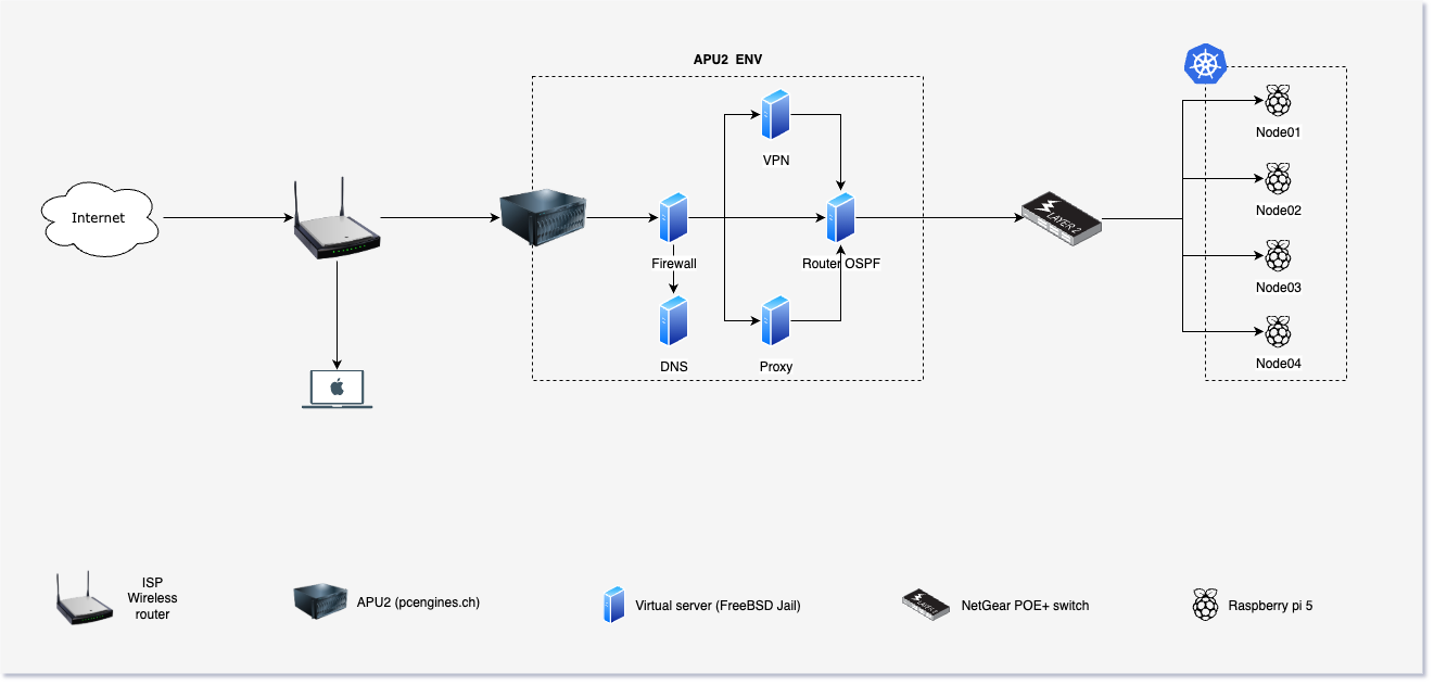
The main idea is to build a home lab using low-power devices and to configure/build all the hardware and software components needed to consume and expose personal services to and from the internet.
Hardware.
| Label | Device | Role |
|---|---|---|
| ISP Wireless router | ISP default | Internet access / port forwarding |
| APU2 | pcengines.ch | Internal router/firewall + virtual servers |
| Virtual Server | FreeBSD Jail | Virtual servers inside the APU2 |
| NetGear POE+ switch | ProSAFE MS510TXPP | Switch + Power over Ethernet for Raspberry Pi nodes |
| Raspberry | Raspberry Pi 5 | Kubernetes node (kubelet) |
Virtual servers
You can think of FreeBSD Jails as the analogue of Docker containers on Linux.
APU2
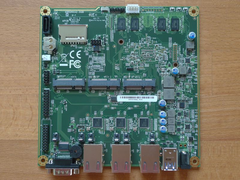
To implement the internal router/firewall I used an APU2 motherboard from pcengines. The main trait of this device is that it is designed as an embedded system: it has no moving parts such as mechanical hard drives, no sockets for plugging in RAM modules, and passive cooling (no fan is required because it is a low-power device). Combined with the advantages of the NanoBSD project, that makes it ideal for this setup.
The APU2 motherboard includes the following features (among others):
- 1 AMD Embedded G series GX-412TC processor, 1 GHz quad Jaguar core with 64 bit 2MB L2 cache.
- 4 GB DRAM (soldered onto the board).
- 1 m-SATA slot.
- 3 Gigabit Ethernet ports.
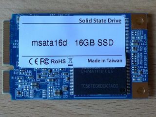
As storage, a solid-state mSATA drive similar to the one shown below was used.
NetGear switch
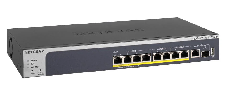
The switch used is the ProSAFE MS510TXPP. I chose this model mainly because of its PoE+ (Power over Ethernet) capabilities, which let me power the Raspberry Pi 5 devices over the network cable (a PoE HAT must be purchased for the Raspberry Pi boards).
The switch has the following features:
Web-based management with the following capabilities:
- VLANs: Supports up to 256 port-based VLANs, IEEE 802.1Q, Auto Voice VLAN, and Auto Video VLAN.
- Static routing (Layer 3 Lite): Supports up to 32 static IPv4 routes and 32 static IPv6 routes, plus an ARP table of up to 512 entries.
- Link aggregation / port trunking: Compatible with IEEE 802.3ad LACP (Link Aggregation Control Protocol).
- Quality of Service (QoS): Traffic prioritization based on ports, IEEE 802.1p, DSCP, TCP/UDP, and DiffServ with WRR (Weighted Round Robin) queues or strict priority.
- Monitoring: SNMP v1, v2c, and v3, RMON (groups 1, 2, 3, and 9), and remote syslog.
Port configuration (10 ports total):
- Standard Gigabit ports (1G): 4 RJ-45 ports (10M/100M/1G) with PoE+ support.
- Multi-Gigabit ports (2.5G): 2 RJ-45 ports (100M/1G/2.5G) with PoE+ support (IEEE 802.3bz / NBASE-T).
- Multi-Gigabit ports (5G): 2 RJ-45 ports (100M/1G/2.5G/5G) with PoE+ support (IEEE 802.3bz / NBASE-T).
- 10G copper uplink: 1 dedicated RJ-45 port (100M/1G/2.5G/5G/10GBASE-T).
- 10G SFP+ fiber uplink: 1 dedicated SFP+ port (1G/10GBASE-X SFP+).
Raspberry Pi 5
Not much to say here: four Raspberry Pi 5 boards were used for the Kubernetes nodes. At the time of writing this article, the official Raspberry Pi product page offers a 16 GB RAM version; the devices used here have half of that, 8 GB of RAM.
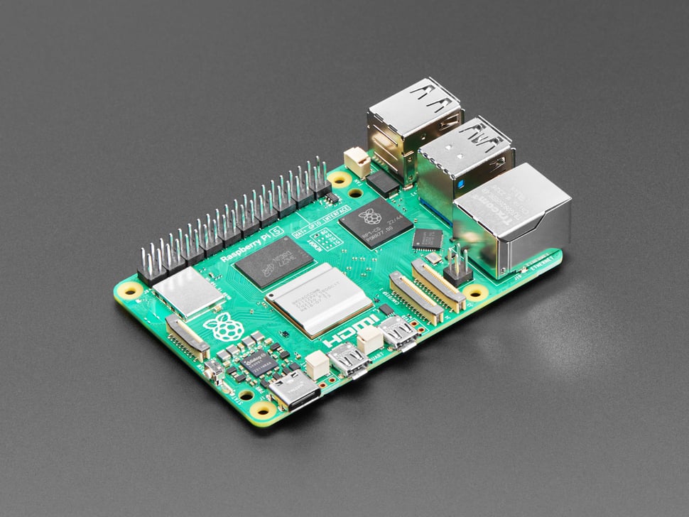
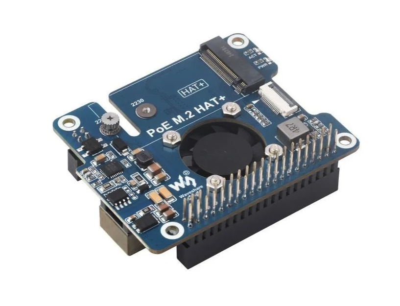
microSD cards are relatively fragile under power outages, so the Kubernetes nodes were fitted with PoE HATs (Power over Ethernet) to achieve two goals: first, replace the microSD card with an m.2 solid-state drive that is more resilient to power cuts; and second, power the Raspberry Pi boards over the network cable. As mentioned earlier, the NetGear MS510TXPP switch can power network devices over the Ethernet connection.
Rack for Kubernetes
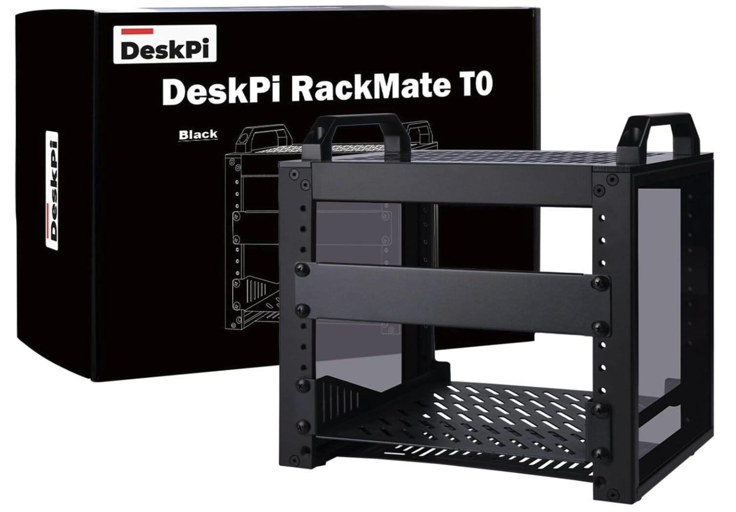
One problem when building a Kubernetes cluster with Raspberry Pi boards is how to organize the devices—both the compute nodes and the router. GeeekPi manufactures racks for Raspberry Pi boards and other accessories to organize this kind of project. The mini-rack chosen for this home lab is the T0 model.
Final setup
Next steps
- Install the NanoBSD image.
- Install Raspberry Pi OS on the Raspberry Pi nodes.
- Create the Kubernetes cluster.